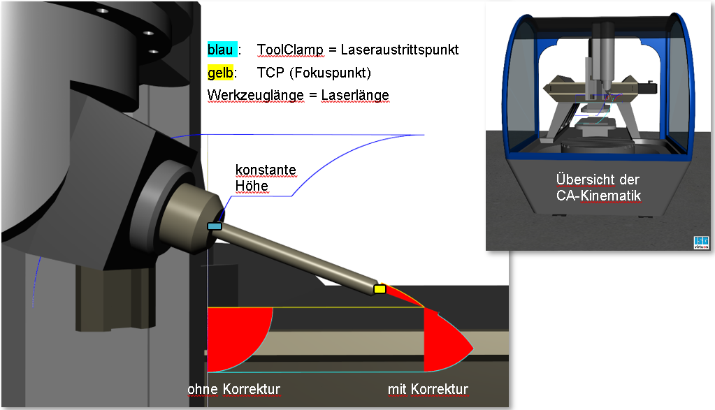
Example: Inclination of tool via CA kinematic
The example below shows the effect of height monitoring at a tool head inclination of 90°. The red area visualises the original “penetration of the laser beam” into the workpiece. The blue line describes the height of the tool head (laser exit point) when the tool is inclined.
No compensation: No tool head height compensation here.
With compensation: starting at the specified angle, the tool head is maintained at a constant height.

The required distance monitoring parameters (Kinematic ID 98) are entered in the NC program:
;DistCtrl-OnOff.nc
; 80 mm tool length
N100 V.G.WZ_AKT.L = 80
; HD1 geometric tool head offset
N200 V.G.KIN_STEP[1].ID[98].PARAM[0] = 1000000
; inclination angle starting at which tool head is maintained constant
N210 V.G.KIN_STEP[1].ID[98].PARAM[1] = 500000
; max. inclination angle up to which the distance is maintained
; constant
N210 V.G.KIN_STEP[1].ID[98].PARAM[2] = 700000
; max. inclination angle starting at which an error is output
N210 V.G.KIN_STEP[1].ID[98].PARAM[3] = 910000
N220 #TRAFO [ 9, 98]
N240 G01 A90 F10