MCV_CamSwitch
The MCV_CamSwitch FB detects the output of a cam-controlled switch that is assigned to an axis. The cam range is freely definable.
The FB-internal calculations are based on a modulo coordinate system with the value range [0, 3600000] 0.1 µm or 10-4 °.
The prerequisite must also be fulfilled that no more than half the modulo value range is traversed by the axis in each PLC cycle.
Block diagram

FB parameters
VAR_IN_OUT | ||
Variable name | Data type | Description |
Axis | AXIS_REF | Axis reference |
VAR_INPUT | ||
Variable name | Data type | Description |
Enable | BOOL | Activates the cam-driven switch. |
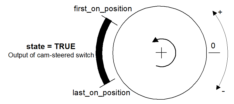
FirstOnPosition | LREAL | Position of the axis at which the output of the cam-driven switch changes from FALSE to TRUE, if the axis moves in a positive direction. Default unit [0.1µm or 10-4 °] |
LastOnPosition | LREAL | Position of the axis at which the output of the cam-driven switch changes from TRUE to FALSE, if the axis moves in a positive direction. Default unit [0.1µm or 10-4 °] |
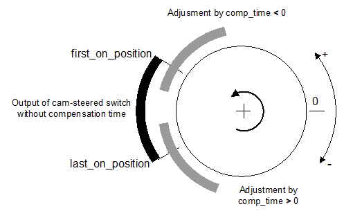
CompTime | LREAL | Compensation time by which the switch-on phase of the switch is advanced or delayed. Default unit [1ms] |
PosType | INT | Selection whether command position or actual position of the axis should be used for comparison with the input variables and for calculation of the switch-on/switch-off position that is changed by the compensation time. 0: Command position of the axis (ACTIVE_POS) 1: Actual position of the axis (CURRENT_POS) |
VAR_OUTPUT | ||
Variable name | Data type | Description |
Active | BOOL | Indicates that the cam-controlled switch is active. |
State | BOOL | Output of the cam-driven switch. The output is TRUE when
|
Error | BOOL | Is TRUE if an error occurs in the FB. |
ErrorID | WORD | Error identifier |
Pulsed | BOOL | For visualisation purposes. If the "State" output is TRUE, the "Pulsed" output is also TRUE for 1 s. |
Behaviour of the FB:
- Input values for “FirstOnPosition“ and “LastOnPosition“ which are less than the lower limit of the modulo coordinate system are set to the lower limit. Input values which are greater than the upper limit are set to the upper limit. This is done internally in the FB without acknowledgement.
- Specification of a compensation time leads in the FB to modification of the switching positions defined by “ FirstOnPosition” and “LastOnPosition”. If values should result for the modified switching positions that are outside the value range of the modulo coordinate system, they are converted to values within the range. This is done internally in the FB without acknowledgement.
- Modification of the switching positions by specifying a compensation time is executed directly in the PLC cycle by transferring them to the “CompTime“ input and takes full effect immediately.
- Specification of the compensation time "CompTime" acts equally on the “FirstOnPosition” and “LastOnPosition”. Positive values for “CompTime“ lead to a situation where the “State” output changes after a delay to reach a switching position. Negative values lead to a situation where the “State” output changes before the switching position is reached.

- Behaviour of the “State” output of the cam-controlled switch and the positions that are transferred to the “FirstOnPosition” and “LastOnPosition” inputs. The axis moves in a positive direction from the low limit of the modulo coordinate system to the high limit.
Case 1: “FirstOnPosition“ < “LastOnPosition“

Case 2: “FirstOnPosition“ > “LastOnPosition“

- The FB takes 2 special cases into account, which result from the fact that the PLC system is a discreet system. These are:
- The axis position at the time tn is before the switch-on position and the axis position at the time tn+1 is after the switch-off position. Therefore, the switching range is less than the distance traversed by the axis in one PLC cycle.
- If the axis position is before the switch-on position at the time tn, specification of a compensation time may result in a situation where the axis position at the time tn+1 is after the switch-off position due to modification of the switch-on points.
- In these special cases, the “State” output becomes TRUE for at least one PLC cycle although it was not detected within one revolution of the axis that the axis position was between switching positions.