Programming
Feedforward control is programmed in the NC program using the modal commands G135, G136 and G137 [PROG].
Selecting feedforward control with G135
Feedforward control is explicitly deactivated every time the program is started. The axis group-specific activation of feedforward control is programmed by the NC command G135.
Weighting of feedforward control with G136
An axis-specific, percentage weighting of the calculated feedforward control variables takes place with G136. It is limited to 100% for all axes. The weighting factors are reset to 100% after every program start. If feedforward control is activated or deactivated during the NC program, the weighting factors remain set to the values set by G136.
For axes with no G136 programmed, the weighting factor remains set to 100%.
It is also possible to enter the selection and weighting of feedforward control in a single block.
Deselecting feedforward control with G137
G137 deactivates axis group-specific feedforward control.
Deactivating individual axes
With axes for which no feedforward control is to be implemented after global selection with G135, a percentage weighting of 0% must be specified with G136 .
Example

Selecting and weighting feedforward control
G135 (Select feedforward control; weighting)
(for all axes 100%)
G136 X80 Y95 Z0 (weighting; here, the Z axis)
(has no feedforward control)
Parameterising spindles
Feedforward control for spindles is also programmed in the NC program using the modal commands G135, G136 and G137 [PROG].
These commands permit the spindle-specific programming of feedforward control. The commands may not be used simultaneously with other spindle-specific commands.
Example

Parameterising spindles
S[G135] (Activate feedforward control for S)
S[G136=80] (Define weighting in %)
S[G137] (Deactivate feedforward control)
S2[G135 G136=90] ( at 90% weighting for S2)
S2[G136=0] (Change weighting to 0%)
S1[G135] (Activate with default weighting 100% for S1)
Delay
The calculation of feedforward values involves a delay of at least one cycle between the interpolator and the position controller.
Attention

Effects of delay on measurement run
In the worst case, an error may occur during a measurement run since the interpolator, which monitors the touch probe stroke, ignores the distance components in the block buffer between the interpolator and position controller.
This can be prevented by increasing the actual stroke of the measuring probe in the parameter P-AXIS-00086 (hub_messtaster).
Examples
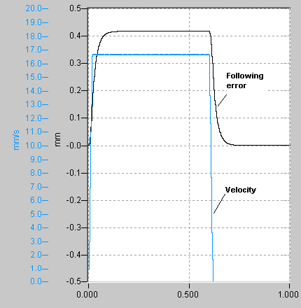
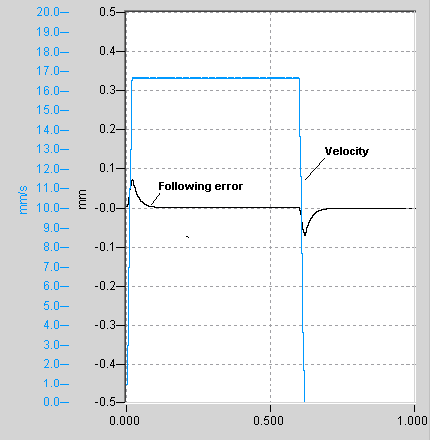
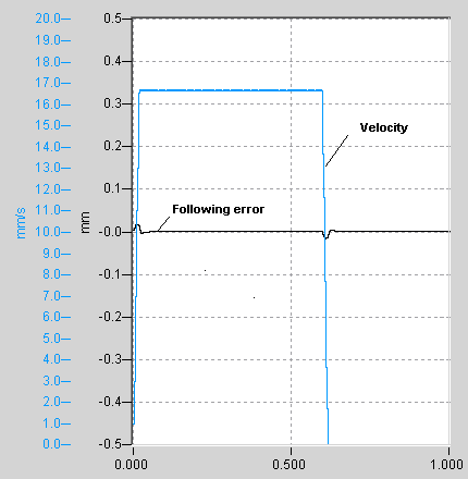
The figures below show the measured position lags with and without speed and acceleration feedforward control for a simple path motion.
The figure below shows a clear position lag over the entire path motion.

When speed feedforward control is activated, position lag peaks only occur in acceleration phases. Within the constant speed range, position lag is fully compensated by feedforward control (see figure below).

Position lag can be further reduced in acceleration phases by means of additional acceleration feedforward control (see figure below).
