KIN_TYP_209 - Tripod with rotary/swivel workpiece table
This kinematic is based on the strut kinematic (KIN_TYP_12) and additionally contains a rotary/swivel workpiece table to carry out conventional 5-axis machining.
Release Note

This kinematic is available as of CNC Build V3.01.3078.
Axis configuration in NC channel | ||
Axis identifier | X, Y, Z (Z1, Z2, Z3), A(B), C | |
Axis index | 0, 1, 2, 3, 4 | |
Kinematic structure | ||
| Tool axes | Workpiece axes |
NC axes | X, Y, Z | A(B), C |


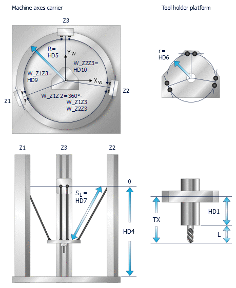
The parameter HD8 is used to toggle between an ideal (1) and non-ideal (0) tripod. An ideal tripod has an angle of 120° between all columns. A non-ideal tripod must be defined by the angles HD9 and HD10.
The third angle between columns is calculated as follows:
W_Z1Z2 = 360° - HD9 – HD10 = 360° - W_Z2Z3 – W_Z1Z3
An angle offset of the rotary/swivel table due to mounting constraints can be compensated by HD30.
Rotary/swivel table – CA variant
HD31 defines the rotary/swivel table variant. By default the parameter is assigned the value 0 defining the CA variant.

CA rotary/swivel table offsets

Rotary/swivel table – CB variant
If HD31 is assigned the value 1, the CB variant is defined.

CB rotary/swivel table offsets

Tripod kinematics offset data
HD offset | param[i] | Description | Unit |
HD1 | 0 | Tool offset Z | 1.0 E-4 mm |
HD2 | 1 | Tool offset Y | 1.0 E-4 mm |
HD3 | 2 | Tool offset X | 1.0 E-4 mm |
HD4 | 3 | Z axis offset machine origin | 1.0 E-4 mm |
HD5 | 4 | Radius to connecting line of the joint centre points on the drive columns (large circle) | 1.0 E-4 mm |
HD6 | 5 | Radius to connecting line of the joint centre points on the holder platform (small circle) | 1.0 E-4 mm |
HD7 | 6 | Strut length to each joint centre point | 1.0 E-4 mm |
HD8 | 7 | Switch to switch over to non-ideal tripod | [ - ] |
HD9 | 8 | Angle of column / joint 3 to column / joint 1 | 1.0 E-4° |
HD10 | 9 | Angle of column / joint 3 to column / joint 2 | 1.0 E-4° |
Offset data of the rotary/swivel table
HD offset | param[i] | Description | Unit |
HD30 | 29 | Angle offset about Z of Cartesian basic system to tripod column Z3 | 1.0 E-4° |
HD31 | 30 | Type of rotary workpiece holder 0: CA, 1:CB Default value = 0 | [ - ] |
HD32 | 31 | X axis offset rotary axis A, (B) to rotary axis C, origin WCS | 1.0 E-4 mm |
HD33 | 32 | Y axis offset rotary axis A, (B) to rotary axis C, origin WCS | 1.0 E-4 mm |
HD34 | 33 | Z axis offset rotary axis A, (B) to rotary axis C, origin WCS | 1.0 E-4 mm |
HD35 | 34 | X offset machine origin MZP to rotary axis A, (B) | 1.0 E-4 mm |
HD36 | 35 | Y offset from machine origin MZP to rotary axis A, (B) | 1.0 E-4 mm |
HD37 | 36 | Z offset machine origin MZP to rotary axis A, (B) | 1.0 E-4 mm |
HD38 | 37 | Rotary offset A (B) axis | 1.0 E-4° |
HD39 | 38 | Rotary offset C axis | 1.0 E-4° |
HD40 | 39 | Rotation direction flag A (B) axis | [ - ] |
HD41 | 40 | Rotation direction flag C axis | [ - ] |