Application example
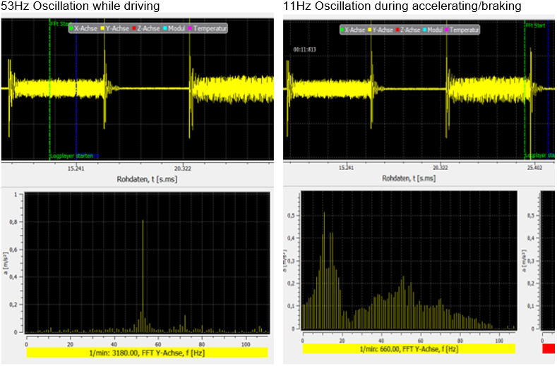
The example below shows the results and parameterisation of the "Improved Position Control" function in an application with a toothed rack and pinion drive.
For trial purposes, the axis was moved forward and backward and vibrations were recorded using an acceleration sensor.

The figure above shows the recorded time range in the upper section and the frequency range in the lower section.
During the process, the axis shows a predominant vibration at a frequency of 53Hz and a predominant vibration at 11Hz during acceleration and deceleration. The task is to damp the two frequencies by using the "Improved Position Control" function.

The figure above shows vibration damping at 53Hz. The amplitude of 0.81m/s2 is damped to 0.40 m/s2 by optimising the “DIRECT” mode parameters.
At the same time, the vibration at 11 Hz is damped by using the "INDIRECT" mode.

The amplitude is also damped from 0.52 m/s2 to 0.28 m/s2 at this frequency by optimising the parameters.
Parameters used
lr_param.improved_position_control.enable TRUE
lr_param.improved_position_control.v_add_max_fact 1000
lr_param.improved_position_control.stage[0].mode DIRECT
lr_param.improved_position_control.stage[0].filter.order 2
lr_param.improved_position_control.stage[0].filter.fg_f0 53
lr_param.improved_position_control.stage[0].filter.q_factor 10
lr_param.improved_position_control.stage[0].filter.damping 0.9
lr_param.improved_position_control.stage[0].weight_fact_num 100
lr_param.improved_position_control.stage[0].weight_fact_denom 200
lr_param.improved_position_control.stage[1].mode INDIRECT
lr_param.improved_position_control.stage[1].filter.order 2
lr_param.improved_position_control.stage[1].filter.fg_f0 90
lr_param.improved_position_control.stage[1].filter.q_factor 10
lr_param.improved_position_control.stage[1].filter.damping 0.5
lr_param.improved_position_control.stage[1].weight_fact_num 100
lr_param.improved_position_control.stage[1].weight_fact_denom 200
lr_param.improved_position_control.stage[2].mode NOT_ACTIVE
lr_param.improved_position_control.stage[2].filter.order 2
lr_param.improved_position_control.stage[2].filter.fg_f0 90
lr_param.improved_position_control.stage[2].filter.q_factor 10
lr_param.improved_position_control.stage[2].filter.damping 0.4
lr_param.improved_position_control.stage[2].weight_fact_num 100
lr_param.improved_position_control.stage[2].weight_fact_denom 200
Procedure explained by example
First enable and observe the modes for the frequencies separately to find the best possible parameters for a frequency.
Select the “DIRECT” mode for the frequency at 53 Hz since the frequency is clearly visible in the drive actual values. Due to the high frequency, the quality factor can be increased accordingly. A quality factor of 10 corresponds to a bandwidth of 5.3Hz at this frequency. Then gradually increase the weighting factor until the result deteriorates again.
The same principle is used to determine the parameters for the frequency at 11Hz. Here the "INDIRECT" mode is used in order to separate the frequency from its adjacent frequencies. An additional damping must be set for this mode. To determine optimum damping, calculate the damping of the vibration from the time range of the recording. Alternatively, observe the behaviour of the "Improved Position Control" function as you gradually lower the damping.
Finally, activate both frequencies simultaneously and check whether the two stages influence each other. Since both frequencies are relatively far apart in this example, no influence is observable.