Parameters
Required input parameters
Input parameters | Description |
@P1 | Workpiece surface, Z position (absolute) |
@P2 | Retraction plane, Z position (absolute) |
@P3 | Safety clearance above workpiece (unsigned), Z distance (relative to the reference plane/machining height) |
@P4 | Engraving depth in workpiece (unsigned), Z distance (relative to the reference plane) |
@P21 | to engraving text |
@P53 | Font size |
Optional input parameters
Input parameters | Description |
@P11 | Feed rate for Z infeeds, F word |
@P12 | Feed rate for engraving movements, F word |
@P13 | Subroutine executed at start of engraving |
@P14 | Subroutine executed at end of engraving |
@P15 | Subroutine executed at start of each character |
@P16 | Subroutine executed at end of each character |
@P17 | Subroutine executed at start of each path |
@P18 | Subroutine executed at end of each path |
@P23 | Invert text (default value = |
@P24 | Use placeholders (default value = |
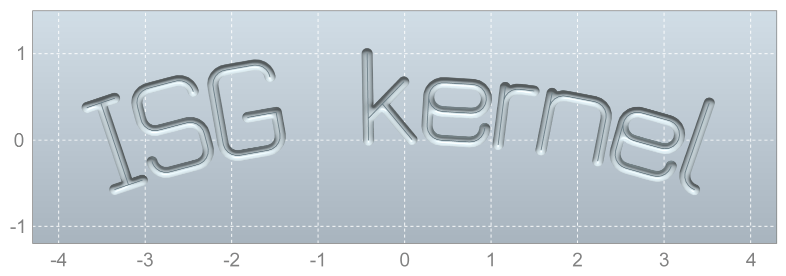
@P31 | Arrangement (default value = 0) 0 = rectangle 1 = arc, circle centre point below text 2 = arc, circle centre point above text |
@P32 | Arrangement parameter 1 if |
@P33 | Arrangement parameter 2 if |
@P41 | Reference point (default value = 6) 0 = top left 1 = top centre 2 = top right 3 = centre left 4 = centre centre 5 = centre right 6 = baseline left 7 = baseline centre 8 = baseline right 9 = bottom left 10 = bottom centre 11 = bottom right |
@P42 | Reference point, X position (default value = |
@P43 | Reference point, Y position (default value = |
@P52 | Determining font size (default value = 0) 0 = height of letter "X" 1 = width of letter "X" 2 = height of entire text 3 = width of entire text |
@P54 | Font weight (default = calculation from engraving depth) Can be specified instead of the engraving depth together with the point angle of the engraving tool. |
@P55 | Point angle of the engraving tool Can be specified instead of the engraving depth together with the font weight. |
@P61 | non-proportional font (default text = |
@P62 | mirror each letter in X direction (default value = |
@P63 | mirror each letter in Y direction (default value = |
@P64 | additional X offset for each letter (default value = 0) |
@P65 | additional Y offset for each letter (default value = 0) |
@P71 | Type of output (default value = 0) 0 = G code, machine is moved 1 = no output, for calculations, size requests, etc. |
@P101 | free parameter |
@P102 | free parameter |
@P103 | free parameter |
It is recommended to use the Syntax check.to verify whether the input parameters are correctly assigned.
Encoding the NC program
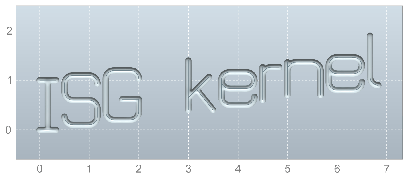
The text “ISG kernel” consists of only ASCII characters. Nothing else needs to be considered when encoding the NC program that calls up the engraving cycle.
However, if you want to use diacritical marks or other special characters, the NC program must be saved in the Windows-1252 encoding.
Programing Example
Engraving special characters
; call engraving cycle for text with special characters
; !!Save the NC program in Windows-1252 encoding!!
L CYCLE [NAME = "SysMillEngrave.ecy" \
@P1 = 0 \
@P2 = 2 \
@P3 = 1 \
@P4 = 0.2 \
@P11 = 2000 \
@P12 = 1000 \
@P21 = "Brühe €1.95" ( Text with special characters ) \
@P53 = 2 \
]
M30

The supplied standard font supports all printable characters in the Windows-1252 character set.
Subroutines
The parameters @P13 to @P18 can specify subroutines that execute specific results.
- Subroutine
@P13is executed before the start of text engraving. - Subroutine
@P14is executed after the end of text engraving. - Subroutine
@P15is executed before engraving each character. - Subroutine
@P16is executed after engraving each character. - Subroutine
@P17is executed each time before leaving the retraction plane to start a new milling section. - Subroutine
@P18is executed each time after a milling section ends and the retraction plane is reached.
Subroutines enable various technologies during engraving,
e.g. the engraving cycle can be used for milling machines as well as for laser or plasma cutting machines. Subroutines @P17 and @P18 could enable or disable the laser.
Invert text
If @P23 is set to TRUE, the input text is output inverted.
Programing Example

Invert text
; call engraving cycle for inverted text
L CYCLE [NAME = "SysMillEngrave.ecy" \
@P1 = 0 \
@P2 = 2 \
@P3 = 1 \
@P4 = 0.2 \
@P11 = 2000 \
@P12 = 1000 \
@P21 = "ISG kernel" \
@P23 = TRUE ( invert text ) \
@P53 = 2 \
]
M30

Placeholders
If @P24 is set to TRUE, placeholders can be used in the transferred text. For example, to engrave the current date, the placeholder ${date} can be used:
Programing Example

Placeholders
; use placeholders
L CYCLE [NAME = "SysMillEngrave.ecy" \
@P1 = 0 \
@P2 = 2 \
@P3 = 1 \
@P4 = 0.2 \
@P11 = 2000 \
@P12 = 1000 \
@P21 = "heute ${date}" ( engrave current date ) \
@P24 = TRUE ( use placeholders ) \
@P53 = 2 \
]
M30

Placeholders supported include
Placeholders | Example | Description |
| 03/12/2021 | current date, YYYY-MM-DD |
| 17:15:43 | current time, hh:mm:ss |
| 2021-12-03 17:15:43 | current date and time, YYYY-MM-DD hh:mm:ss |
| 2021 | current year, YYYY |
| 12 | current month, MM |
| 03 | current day, DD |
| 17 | current hour, hh |
| 15 | current minute, mm |
| 43 | current second, ss |
| SysMillEngraveDemo.nc | Filename of the calling NC main program |
| EngraveDemo | Name (%…) of the calling NC main program |
| 11 | Value of cycle parameter |
| 22 | Value of cycle parameter |
| 33 | Value of cycle parameter |
Programing Example

Placeholders
; use placeholders for free parameters
L CYCLE [NAME = "SysMillEngrave.ecy" \
@P1 = 0 \
@P2 = 2 \
@P3 = 1 \
@P4 = 0.2 \
@P11 = 2000 \
@P12 = 1000 \
@P21 = "${1} + ${2} = ${3}" \
@P24 = TRUE ( use placeholders ) \
@P53 = 1 \
@P101 = 11 ( free parameter ) \
@P102 = 22 ( free parameter ) \
@P103 = 33 ( free parameter ) \
]
M30

Layout and reference point
The parameter @P31 determines the layout of the engraved text.
Linear (default value)
By default @P31 = 0 the text is output in one line in the usual form. The surrounding character box is positioned by a reference point. The following intersections are possible as a reference point.
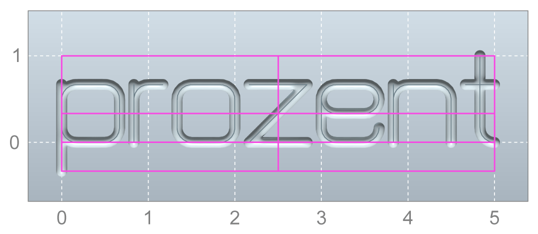
The reference point is specified by the parameter @P41 and can assume the following values.
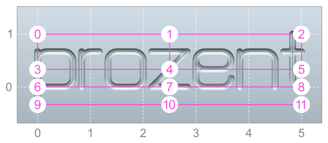
The reference point coordinates (X, Y) are specified by (@P42, @P43). By default these parameters are pre-assigned the current axis positions.
Programing Example

Engrave linear
; reference point (centre, centre) where (1, -0.25)
L CYCLE [NAME = "SysMillEngrave.ecy" \
@P1 = 0 \
@P2 = 2 \
@P3 = 1 \
@P4 = 0.2 \
@P11 = 2000 \
@P12 = 1000 \
@P21 = "ISG kernel" \
@P41 = 4 ( reference point, centre, centre ) \
@P42 = 1 ( reference point X coordinate ) \
@P43 = -0.25 ( reference point Y coordinate ) \
@P53 = 2 \
]
M30

Arc
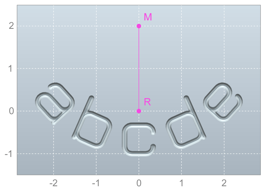
Where @P31 = 1 and @P31 = 2, the characters can be arranged in the form of an arc.
In addition to the reference point R, the parameters (@P32, @P33) specify the circle centre point M.
Programing Example

Engrave in arc
; reference point (centre, bottom) and circle centre point (0, -2)
L CYCLE [NAME = "SysMillEngrave.ecy" \
@P1 = 0 \
@P2 = 2 \
@P3 = 1 \
@P4 = 0.2 \
@P11 = 2000 \
@P12 = 1000 \
@P21 = "abcde" \
@P31 = 1 ( circle layout ) \
@P32 = 0 ( circle centre point X ) \
@P33 = -2 ( circle centre point Y ) \
@P41 = 10 ( reference point centre, bottom ) \
@P42 = 0 ( reference point X ) \
@P43 = 0 ( reference point Y ) \
@P53 = 2 \
]
M30
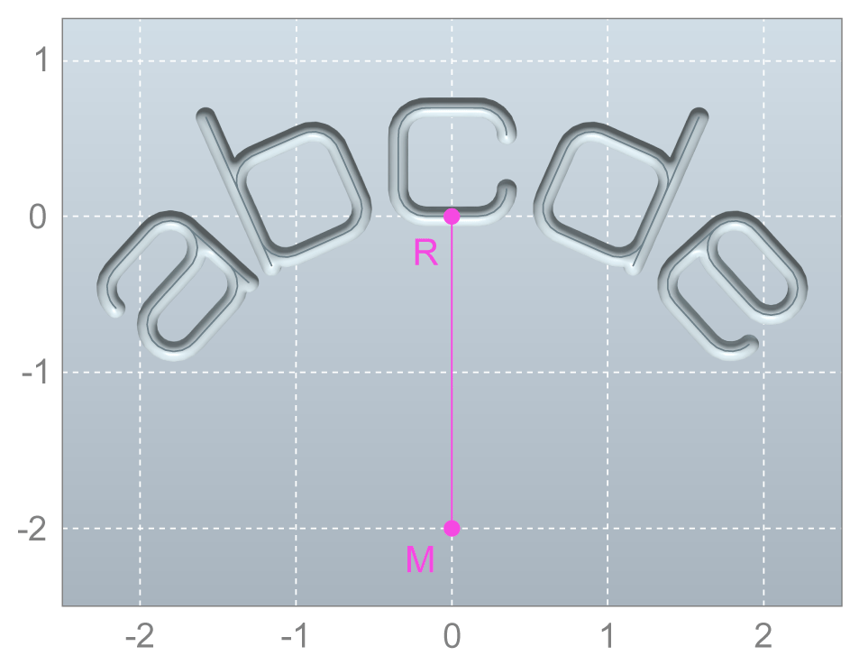
When reference point and circle centre point are identical, an error is output.
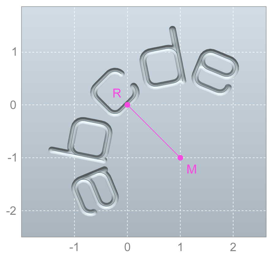
Example: varied circle centre point
Programing Example

Engrave in arc
; reference point (centre, bottom) and circle centre point (1, -1)
L CYCLE [NAME = "SysMillEngrave.ecy", \
@P1 = 0 \
@P2 = 2 \
@P3 = 1 \
@P4 = 0.2 \
@P11 = 2000 \
@P12 = 1000 \
@P21 = "abcde" \
@P31 = 1 ( circle layout ) \
@P32 = 1 ( circle centre point X ) \
@P33 = -1 ( circle centre point Y ) \
@P41 = 10 ( reference point centre, bottom ) \
@P42 = 0 ( reference point X ) \
@P43 = 0 ( reference point Y ) \
@P53 = 2 \
]
M30
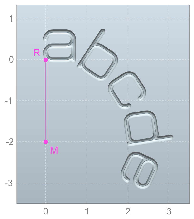
Example: Reference point (left, bottom)
Programing Example

Reference point (left, bottom)
; reference point (left, bottom) and circle centre point (0, -2)
L CYCLE [NAME = "SysMillEngrave.ecy" \
@P1 = 0 \
@P2 = 2 \
@P3 = 1 \
@P4 = 0.2 \
@P11 = 2000 \
@P12 = 1000 \
@P21 = "abcde" \
@P31 = 1 ( circle layout ) \
@P32 = 0 ( circle centre point X ) \
@P33 = -2 ( circle centre point Y ) \
@P41 = 9 ( reference point left, bottom ) \
@P42 = 0 ( reference point X ) \
@P43 = 0 ( reference point Y ) \
@P53 = 2 \
]
M30
Example: Circle centre point is above text
In the above examples, the circle centre point was always below the text. Therefore, the text start and end were both with “curved downwards”. Use @P31 = 2 to achieve the opposite effect. The circle centre point is above the text and the text ends are “curved upwards”.
Programing Example

Circle centre point above text
; circle centre point is above text
L CYCLE [NAME = "SysMillEngrave.ecy" \
@P1 = 0 \
@P2 = 2 \
@P3 = 1 \
@P4 = 0.2 \
@P11 = 2000 \
@P12 = 1000 \
@P21 = "abcde" \
@P31 = 2 ( circle layout 2 ) \
@P32 = 0 ( circle centre point X ) \
@P33 = 2 ( circle centre point Y ) \
@P41 = 1 ( reference point, centre, top ) \
@P42 = 0 ( reference point X ) \
@P43 = 0 ( reference point Y ) \
@P53 = 2 \
]
M30
Font size
The font size can either be specified directly or derived from another size. The parameter @P52 determines how the font size is calculated. The following options are available.
Value of @P52 | Meaning |
0 (default) | height of letter "X" |
1 | width of letter "X" |
2 | height of entire text (in linear layout) |
3 | width of entire text (in linear layout) |
The corresponding size is then specified in @P53.
Example: height of letter "X"
Programing Example

height of letter X
; font size via the height of "X"
L CYCLE [NAME = "SysMillEngrave.ecy" \
@P1 = 0 \
@P2 = 2 \
@P3 = 1 \
@P4 = 0.2 \
@P11 = 2000 \
@P12 = 1000 \
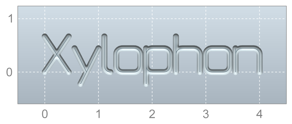
@P21 = "Xylophone" \
@P52 = 0 ( height of “X” ) \
@P53 = 2 ( font size 1 ) \
]
M30
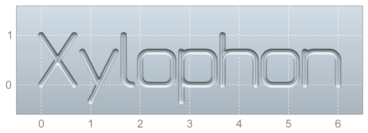
Example: width of letter "X"
Programing Example

width of letter X
; font size via the width of "X"
L CYCLE [NAME = "SysMillEngrave.ecy" \
@P1 = 0 \
@P2 = 2 \
@P3 = 1 \
@P4 = 0.2 \
@P11 = 2000 \
@P12 = 1000 \
@P21 = "Xylophone" \
@P52 = 1 ( width of “X” ) \
@P53 = 2 ( font size 1 ) \
]
M30
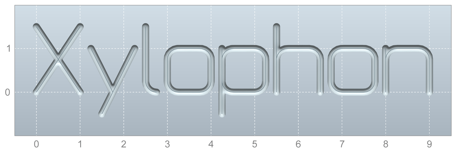
Example: height of entire text
Programing Example

height of entire text
; font size via the height of the entire text
L CYCLE [NAME = "SysMillEngrave.ecy" \
@P1 = 0 \
@P2 = 2 \
@P3 = 1 \
@P4 = 0.2 \
@P11 = 2000 \
@P12 = 1000 \
@P21 = "Xylophone" \
@P52 = 2 ( height of entire text ) \
@P53 = 2 ( font size 1 ) \
]
M30
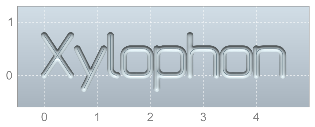
Example: width of entire text
Programing Example

width of entire text
; font size via the width of the entire text
L CYCLE [NAME = "SysMillEngrave.ecy" \
@P1 = 0 \
@P2 = 2 \
@P3 = 1 \
@P4 = 0.2 \
@P11 = 2000 \
@P12 = 1000 \
@P21 = "Xylophone" \
@P52 = 3 ( width of entire text ) \
@P53 = 4 ( font size 4 ) \
]
M30
Non-proportional font
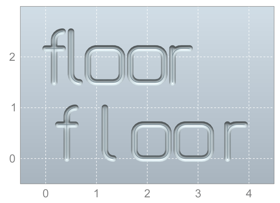
The parameter @P61 switches over to non-proportional font. In this mode, all characters have the same width.
Programing Example

Non-proportional font
; proportional font
L CYCLE [NAME = "SysMillEngrave.ecy" \
@P1 = 0 \
@P2 = 2 \
@P3 = 1 \
@P4 = 0.2 \
@P11 = 2000 \
@P12 = 1000 \
@P21 = "floor" \
@P42 = 0 ( reference point X ) \
@P43 = 1.5 ( reference point Y ) \
@P53 = 2 \
@P63 = FALSE ( proportional font ) \
]
; non-proportional font
L CYCLE [NAME = "SysMillEngrave.ecy" \
@P1 = 0 \
@P2 = 2 \
@P3 = 1 \
@P4 = 0.2 \
@P11 = 2000 \
@P12 = 1000 \
@P21 = "floor" \
@P42 = 0 ( reference point X ) \
@P43 = 0 ( reference point Y ) \
@P53 = 2 \
@P61 = TRUE ( non-proportional font ) \
]
M30
Mirror font
The parameters @P62 and @P63 can mirror the characters in the X and Y directions.
Example: Mirror in X, character by character
Programing Example

Mirror in X - character by character
; mirror in X, character by character
L CYCLE [NAME = "SysMillEngrave.ecy" \
@P1 = 0 \
@P2 = 2 \
@P3 = 1 \
@P4 = 0.2 \
@P11 = 2000 \
@P12 = 1000 \
@P21 = "ISG kernel" \
@P53 = 2 \
@P62 = TRUE ( mirror text in X ) \
]
M30

Example: Mirror in X, complete
Programing Example

Mirror in X - mirror
If only @P62 is used to mirror in X, only each character is mirrored separately, but the order of the characters remains unchanged. To mirror the text completely, use @P23 in addition for text inversion.
; mirror in X, complete
L CYCLE [NAME = "SysMillEngrave.ecy" \
@P1 = 0 \
@P2 = 2 \
@P3 = 1 \
@P4 = 0.2 \
@P11 = 2000 \
@P12 = 1000 \
@P21 = "ISG kernel" \
@P23 = TRUE ( invert text ) \
@P53 = 2 \
@P62 = TRUE ( mirror text in X ) \
]
M30

Example: Mirror in Y
Programing Example

Mirror in Y
; mirror in Y
L CYCLE [NAME = "SysMillEngrave.ecy" \
@P1 = 0 \
@P2 = 2 \
@P3 = 1 \
@P4 = 0.2 \
@P11 = 2000 \
@P12 = 1000 \
@P21 = "ISG kernel" \
@P53 = 2 \
@P63 = TRUE ( mirror text in Y ) \
]
M30

Letter spacing
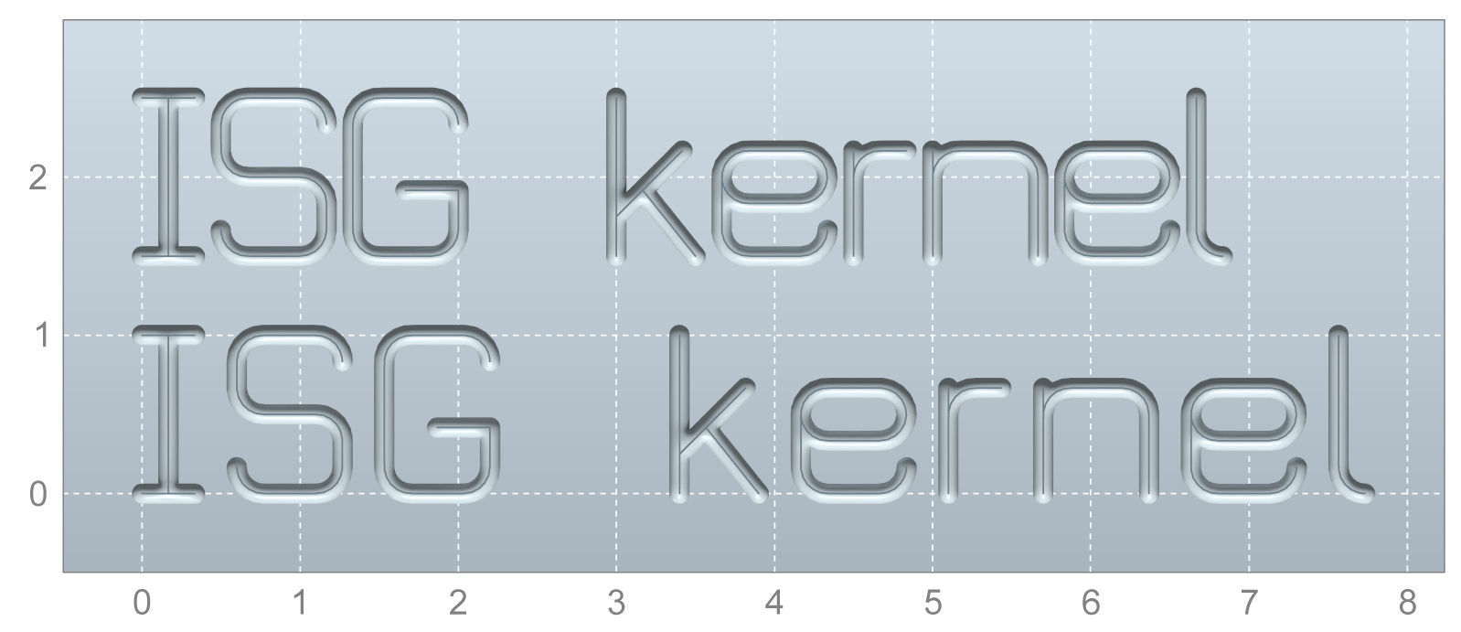
Character spacing can be influenced by the parameters @P64 in X and @P65 in Y.
Example: X spacing with large tool radius
It may be advantage to increase the spacing, especially in X, if large tool radii are used
Programing Example

X spacing with large tool radius
; normal spacing in X
L CYCLE [NAME = "SysMillEngrave.ecy" \
@P1 = 0 \
@P2 = 2 \
@P3 = 1 \
@P4 = 0.2 \
@P11 = 2000 \
@P12 = 1000 \
@P21 = "ISG kernel" \
@P42 = 0 ( reference point X ) \
@P43 = 1.5 ( reference point Y ) \
@P53 = 2 \
@P64 = 0 ( normal X spacing ) \
]
; adapt spacing in X
L CYCLE [NAME = "SysMillEngrave.ecy" \
@P1 = 0 \
@P2 = 2 \
@P3 = 1 \
@P4 = 0.2 \
@P11 = 2000 \
@P12 = 1000 \
@P21 = "ISG kernel" \
@P42 = 0 ( reference point X ) \
@P43 = 0 ( reference point Y ) \
@P53 = 2 \
@P64 = 0.1 ( increase X spacing by 0.1 ) \
]
M30
Example: Y spacing for staircase effect
A staircase effect is obtainable with a Y offset.
Programing Example

Y spacing for staircase effect
; staircase effect in Y
L CYCLE [NAME = "SysMillEngrave.ecy" \
@P1 = 0 \
@P2 = 2 \
@P3 = 1 \
@P4 = 0.2 \
@P11 = 2000 \
@P12 = 1000 \
@P21 = "ISG kernel" \
@P53 = 2 \
@P65 = 0.1 ( Y spacing ) \
]
M30
