Programming
Measurement results, V.A.MESS.<axis> V.A.MERF.<axis> V.A.MOFFS.<axis> V.A.MEIN.<axis>
When a measurement is executed by the NC command G100/G310, an axis position is stored after a measuring probe is triggered. After the measurement interrupt is triggered, the current position is stored (latched) and the measurement run may then be ended.
The positions recorded by the measurement process can be used in the NC program by G101/G102 (calculation of the measurement offset) and special axis-specific variables.
Examples:
V.A.MESS.X | Measured value of axis X in the coordinate system in which the measurement took place, including all offsets. |
V.A.MERF.X | Measurement terminated (TRUE/FALSE). Indicates whether the measurement interrupt is received before the target position is reached. |
V.A.MOFFS.X | Distance between probing position and programmed target position. |
V.A.MEIN.X | The current measurement offset of the X axis including the calculation by G101. This acts as an additive offset of the programmed position: PCS’ = PCS + measurement offsetG101 |
V.G.MEAS_TYPE | Value of currently active measuring type [as of V2.11.2022.03] For further information on the measurement function, refer to the program manual [PROG// Chapter Measurement functions]. |
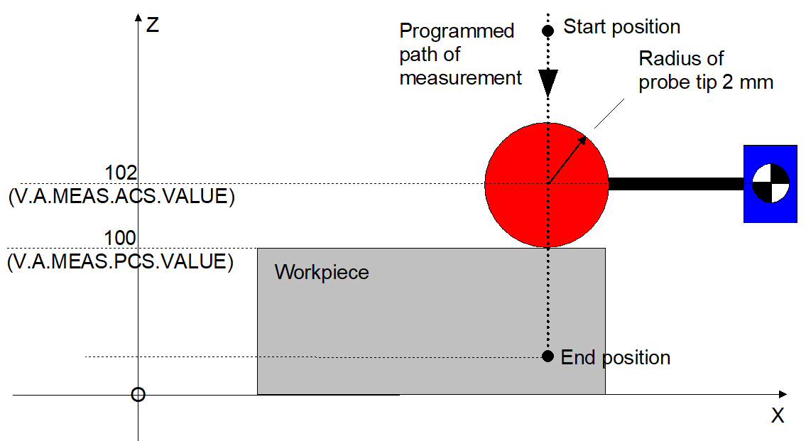
V.A.MEAS.ACS.VALUE.<axis> V.A.MEAS.PCS.VALUE.<axis> | As of Build V2.11.2020.07, the axis-specific variables V.A.MEAS.ACS.VALUE and V.A.MEAS.PCS.VALUE supplement the variable V.A.MESS. The additional variables supply the measured value both in the axis coordinate system including all offsets as well as the measured value in the programming coordinate system. |
Examples:
V.A.MEAS.ACS.VALUE.X | Measured value of axis X in the axis coordinate system (ACS). The value contains all offsets. |
V.A.MEAS.PCS.VALUE.X | Measured value of axis X in the program coordinate system (PCS). The value does not contain any offsets. The ball radius of the measuring probe includes the tool radius specification in the calculation of the PCS value (see example below). The inclusion of the ball radius in the calculation is controlled in the channel parameter P-CHAN-00311. |
Programing Example

Measuring with a measuring probe tool of 2mm radius
%meas_example
:
;Measuring probe tool
;with radius 2 mm
D1
:
G0 X150 Z200
G100 Z20
:
M30
Include the measurement offset in calculations with G101, G102
In the NC program, use
Syntax: | |
G101 <axis_name><fact> { <axis_name><fact> } | non-modal |
may include an offset.
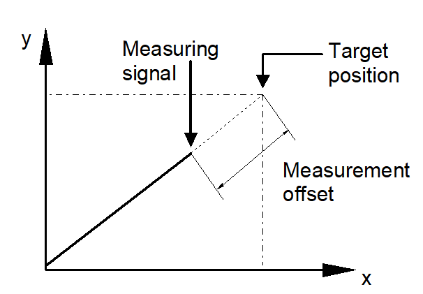
The measurement offset is the distance between the recorded probing position and the programmed target position. It is calculated as follows:
Measurement offset = measuring point – target point
For programmed coordinates, the measurement offset determined from the measured values is included in the calculation of a further offset between programmed and absolute coordinates. An error message is output if no measured values were detected beforehand. The numeral after the axis designation represents the inclusion factor.
The offset caused by the measurement offset is valid until it is deselected by G102.
Syntax: | |
G102 { <axis_name><dummy_expr> } | non-modal |
Notice

If several measurement runs are programmed in sequence, the axis-specific variable V.A.MERF when used considers that the values from the previous measurement are retained for non-programmed axes.
The following relationships apply to the calculation of V.A.MESS.*, V.A.MEAS.* and V.A.MOFFS.* (example for X axis):
V.A. | Without | With Cartesian | With kinematic |
MESS.X | ACS position (includes all | Conversion of | Conversion of |
MEAS.ACS.VALUE.X | ACS position (includes all | ACS position (includes all | ACS position (includes all |
MEAS.PCS.VALUE.X | ACS position (without | Conversion of | Conversion of |
MOFFS.X | = V.A.MESS.X | = V.A.MESS.X | = V.A.MESS.X |
Programing Example

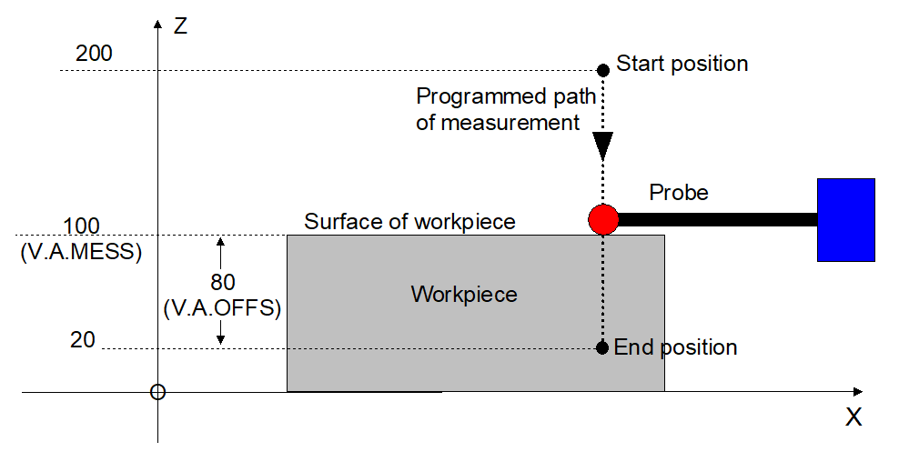
Measure in ACS without offsets.
The programming examples below assume an ideal measuring probe with a ball radius of 0 mm.
Assuming: Measuring probe is triggered at ACS position Z=100.
%meas1
N05 #MEAS MODE[1]
N10 G01 G90 Z200 F2000
N20 G100 Z20 F2000
N30 #MSG SYN["V.A.MESS.Z=%f", V.A.MESS.Z]
-> V.A.MESS.Z = 100.0
N31 #MSG SYN["V.A.MEAS.ACS.VALUE.Z=%f",
V.A.MEAS.ACS.VALUE.Z]
-> V.A.MEAS.ACS.VALUE.Z = 100.0
N32 #MSG SYN["V.A.MEAS.PCS.VALUE.Z=%f",
V.A.MEAS.PCS.VALUE.Z]
-> V.A.MEAS.PCS.VALUE.Z = 100.0
N40 #MSG SYN["V.A.MOFFS.Z=%f", V.A.MOFFS.Z]
-> V.A.MOFFS.Z = 80.0
N50 #MSG SYN["V.A.MEIN.Z=%f", V.A.MEIN.Z]
-> V.A.MEIN.Z = 0.0
N60 G101 Z1
N70 #MSG SYN["V.A.MEIN.Z=%f", V.A.MEIN.Z]
-> V.A.MEIN.Z = 80.0
N80 G01 Z100 F1000
N90 #MSG SYN["V.A.ABS.Z=%f", V.A.ABS.Z]
-> V.A.ABS.Z = 180.0
N100 G102 Z1
N110 #MSG SYN["V.A.MEIN.Z=%f", V.A.MEIN.Z]
-> V.A.MEIN.Z = 0.0
N120 G01 Z100 F1000
N130 #MSG SYN["V.A.ABS.Z=%f", V.A.ABS.Z]
-> V.A.ABS.Z = 100.0
N140 M30
Programing Example

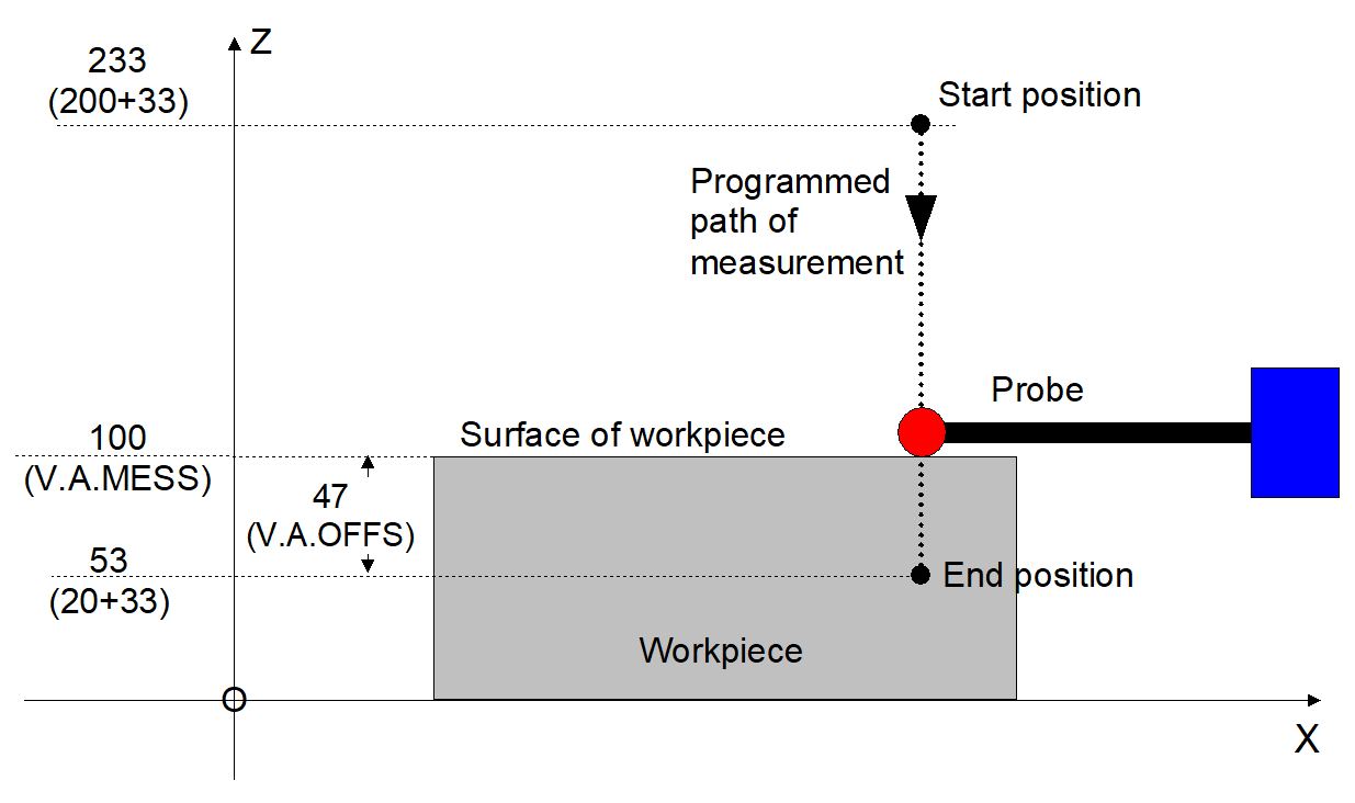
Measure in the ACS with reference point offset
Measure with reference point offset, G92
Assuming: Measuring probe is triggered at ACS position Z=100.
%meas2
N05 #MEAS MODE[1]
N10 G92 Z33
N20 G01 G90 Z200 F2000
N30 G100 Z20 F2000
N40 #MSG SYN["V.A.MESS.Z=%f", V.A.MESS.Z]
-> V.A.MESS.Z = 100.0
N41 #MSG SYN["V.A.MEAS.ACS.VALUE.Z=%f",
V.A.MEAS.ACS.VALUE.Z]
-> V.A.MEAS.ACS.VALUE.Z = 100.0
N42 #MSG SYN["V.A.MEAS.PCS.VALUE.Z=%f",
V.A.MEAS.PCS.VALUE.Z]
-> V.A.MEAS.PCS.VALUE.Z = 67.0
N50 #MSG SYN["V.A.MOFFS.Z=%f",
V.A.MOFFS.Z]
-> V.A.MOFFS.Z = 47.0
N60 #MSG SYN["V.A.MEIN.Z=%f", V.A.MEIN.Z]
-> V.A.MEIN.Z = 0.0
N70 G101 Z1
N80 #MSG SYN["V.A.MEIN.Z=%f", V.A.MEIN.Z]
-> V.A.MEIN.Z = 47.0
N90 G01 Z100 F1000
N100 #MSG SYN["V.A.ABS.Z=%f", V.A.ABS.Z]
-> V.A.ABS.Z = 180.0
N110 G102 Z1
N120 #MSG SYN["V.A.MEIN.Z=%f", V.A.MEIN.Z]
-> V.A.MEIN.Z = 0.0
N130 G01 Z100 F1000
N140 #MSG SYN["V.A.ABS.Z=%f", V.A.ABS.Z]
-> V.A.ABS.Z = 133.0
N150 M30
Programing Example

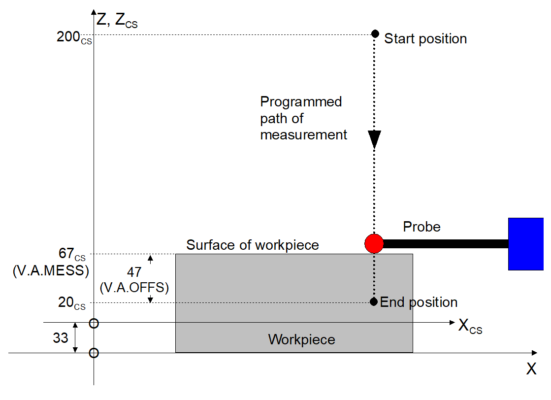
Measure with CS, offset only
Measure with machining coordinate system CS, offset.
Assuming: Measuring probe is triggered at ACS position Z=100.
%meas3
N05 #MEAS MODE[1]
N10 #CS ON[0,0,33,0,0,0]
N20 G01 G90 Z200 F2000
N30 G100 Z20 F2000
N40 #MSG SYN["V.A.MESS.Z=%f", V.A.MESS.Z]
-> V.A.MESS.Z = 67.0
N41 #MSG SYN["V.A.MEAS.ACS.VALUE.Z=%f",
V.A.MEAS.ACS.VALUE.Z]
-> V.A.MEAS.ACS.VALUE.Z = 100.0
N42 #MSG SYN["V.A.MEAS.PCS.VALUE.Z=%f",
V.A.MEAS.PCS.VALUE.Z]
-> V.A.MEAS.PCS.VALUE.Z = 67.0
N50 #MSG SYN["V.A.MOFFS.Z=%f", V.A.MOFFS.Z]
-> V.A.MOFFS.Z = 47.0
N60 #MSG SYN["V.A.MEIN.Z=%f", V.A.MEIN.Z]
-> V.A.MEIN.Z = 0.0
N70 G101 Z1
N80 #MSG SYN["V.A.MEIN.Z=%f", V.A.MEIN.Z]
-> V.A.MEIN.Z = 47.0
N90 G01 Z100 F1000
N100 #MSG SYN["V.A.ABS.Z=%f", V.A.ABS.Z]
-> V.A.ABS.Z = 147.0
N110 G102 Z1
N120 #MSG SYN["V.A.MEIN.Z=%f", V.A.MEIN.Z]
-> V.A.MEIN.Z = 0.0
N130 G01 Z100 F1000
N140 #MSG SYN["V.A.ABS.Z=%f", V.A.ABS.Z]
-> V.A.ABS.Z = 100.0
N150 #CS OFF
N160 M30
Programing Example

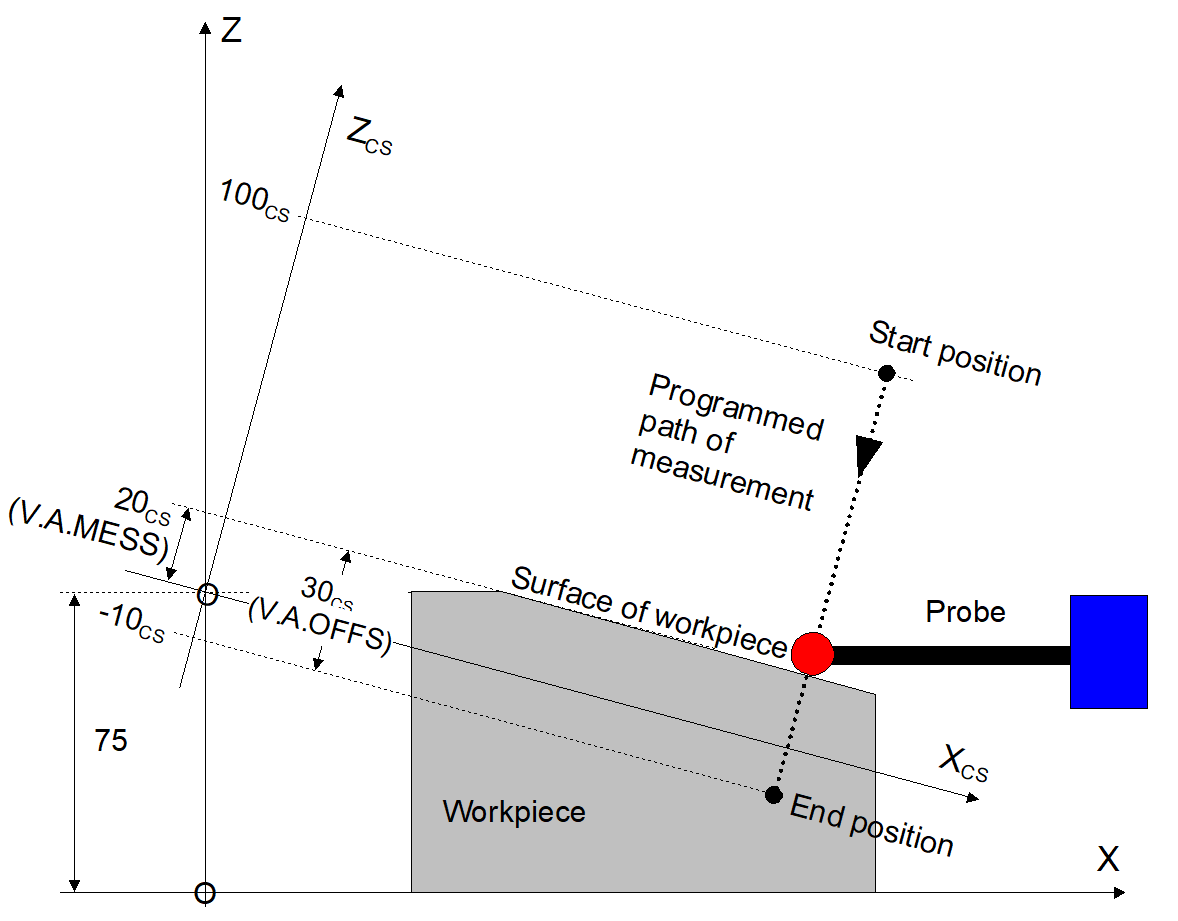
Measure with CS, offset and rotation
Measure with machining coordinate system CS, offset and rotation.
Assuming: Measuring probe is triggered at Z ACS position 55.5mm.
%meas4
N05 #MEAS MODE[1]
N10 #CS ON[0,0,75,0,15,0]
N20 G01 G90 X150 Z100 F2000
N30 G100 Z-10 F1000
N40 #MSG SYN["V.A.MESS.Z=%f", V.A.MESS.Z]
-> V.A.MESS.Z = 20.0
N41 #MSG SYN["V.A.MEAS.ACS.VALUE.Z=%f",
V.A.MEAS.ACS.VALUE.Z]
-> V.A.MEAS.ACS.VALUE.Z = 55.5
N42 #MSG SYN["V.A.MEAS.PCS.VALUE.Z=%f",
V.A.MEAS.PCS.VALUE.Z]
-> V.A.MEAS.PCS.VALUE.Z = 20.0
N50 #MSG SYN["V.A.MOFFS.Z=%f", V.A.MOFFS.Z]
-> V.A.MOFFS.Z = 30.0
N60 #MSG SYN["V.A.MEIN.Z=%f", V.A.MEIN.Z]
-> V.A.MEIN.Z = 0.0
N70 G101 Z1
N80 #MSG SYN["V.A.MEIN.Z=%f", V.A.MEIN.Z]
-> V.A.MEIN.Z = 30.0
N90 G01 Z50 F1000
N100 #MSG SYN["V.A.ABS.Z=%f", V.A.ABS.Z]
-> V.A.ABS.Z = 80.0
N110 G102 Z1
N120 #MSG SYN["V.A.MEIN.Z=%f", V.A.MEIN.Z]
-> V.A.MEIN.Z = 0.0
N130 G01 Z50 F1000
N140 #MSG SYN["V.A.ABS.Z=%f", V.A.ABS.Z]
-> V.A.ABS.Z = 50.0
N150 #CS OFF
N160 M30
