Extended working data: TcNcTrafoParameterExtCnc
Parameters of the methods
Type = EcNcTrafoParameter_ExtCnc
The parameters for the individual methods are transferred via the following extended structure TcCnCTrafoParameter . The data structure provided by the CNC is identified by this parameter type.
Type = EcNcTrafoParameter_ExtCnc
struct TcCncTrafoParameter : public TcNcTrafoParameter, TcCncParam
unsigned short kin_id; // in: used kinematic ID
unsigned long control; // in: control trafo calculation, e.g. EcCncTrafoCtrl_cartesianTrafoInactive
EcCncTrafoOption ret_option; // out: select option of transformation during TrafoSupported()
TcCncVersion CncInterfaceVersion; // Interface version TcCncVersionMajor.TcCncVersionMinor
// orientation
EcCnc_TrafoOriModeActual actual_orientation_mode; // Treatment of orientation, actual rotation sequence
EcCnc_TrafoModeSupported supported_modes; // modes supported by the TcCOM transformation
Note:
The structure element EcCnc_TrafoModeSupported supported_modes replaces the previous element EcCnc_TrafoOriModeSupported supported_orientation_modes. However, the data item is still supported for downward compatibility reasons.
// modulo configuration
ULONG dim_modulo; // dim of modulo vector
EcCnc_McsModulo * mcs_modulo;
EcCnc_AcsModulo * acs_modulo;
Caller identification
The active kinematic transformation is currently used at several points in the CNC: The different callers are noted in the working data transferred to the transformation.
0 : EcCncTrafoCallerID_Undefined
1 : EcCncTrafoCallerID_Decode
2 : EcCncTrafoCallerID_ToolRadiusCorrection
3 : EcCncTrafoCallerID_PathPreparation
4 : EcCncTrafoCallerID_Interpolation
5 : EcCncTrafoCallerID_Display
6 : EcCncTrafoCallerID_BlockSearch
Notice

The caller’s identifier (caller_id) is used to calculate the transformation at various points with variants.
For examples, see Applying and using the Caller ID
Transformation options
While the transformation is initialised (TrafoSupported method), you can select individual CNC options. These options change the CNC interface management and may supply additional parameters. Each of the options is predefined by the CNC and must match the corresponding transformation. The following options are available:
0 : EcCncTrafoOption_None
1 : EcCncTrafoOption_Interpolation_AddInput
Control input
The following data is transferred cyclically to the kinematic transformation
0x0000 0001 EcCncTrafoCtrl_cartesianTrafoInactive
Cartesian transformation is inactive in the CNC. The angle is specified directly by the CNC.
0x0000 0010 EcCncTrafoCtrl_RTCPMode
RTCP mode is requested for a singular kinematic transformation. The angle is also specified directly by the CNC in the singular axis position.
These two items of control information as mentioned above can be used to switch handling in the singularity within the TcCOM transformation, for example. In such cases, the angle is specified directly by the CNC.
As another example (where both control information items listed above not set), the angle input values are assigned via a tool direction vector in angular representation, e.g. for a CA head: C: +-180 degrees, A: 0… 90 degrees.
Version number of CNC interface
In the TcCncVersion data item, the CNC transfers the version number of the transformation interface it uses:
struct TcCncVersion
{
Long major;
Long minor;
};
Further information on version number: Version identifier of transformation interface
Rotation sequence
In the actual_rotation_mode data item, the CNC transfers the active rotation sequence of the orientation axes:
EcCncTrafoOri_None = 0
EcCncTrafoOri_YPR = 1
EcCncTrafoOri_CBC1 = 2
EcCncTrafoOri_CBA = 3
EcCncTrafoOri_CAB = 4
EcCncTrafoOri_AB = 5
EcCncTrafoOri_BA = 6
EcCncTrafoOri_CA = 7
EcCncTrafoOri_CB = 8
The rotation sequences supported in the transformation are transferred to the CNC in the data item supported_rotation_modes (see also Rotation sequence):
typedef struct _EcCnc_TrafoModeSupported
{
unsigned long f_YPR : 1;
unsigned long f_CBC1 : 1;
unsigned long f_CBA : 1;
unsigned long f_CAB : 1;
unsigned long f_UniqueTrafo : 1;
unsigned long f_AB : 1;
unsigned long f_BA : 1;
unsigned long f_CA : 1;
unsigned long f_CB : 1;
unsigned long f_SingularOri : 1;
} EcCnc_TrafoModeSupported;
Unique CNC --> TcCOM transformation
The flag f_UniqueTrafo in the data item supported_modes allows the user to mark the TcCOM transformation as unique in forward and backward directions. The user sets the flag in the TrafoSupported method. By default, the CNC handles TcCOM transformations as not unique. The flag f_UniqueTrafo is checked when the transformation is initialised.
Setting the flag accelerates by a few cycles all operations where the CNC must read the positions of the drives. Such operations include selecting or deselecting the transformation, changing coordinate systems when a TcCOM transformation is active or using V.A.ACS.ABS variables.
Example code to set the flag:
virtual HRESULT TCOMAPI TrafoSupported(PTcCncTrafoParameter p, bool fwd)
{
p->supported_modes.f_UniqueTrafo = TRUE;
return S_OK;
};
Singular TcCOM transformation
The flag f_SingularOr in the data item supported_modes allows the user to mark the TcCOM transformation as a kinematic with a singular head position. The user sets the flag in the TrafoSupported method. The CNC then activates singularity handling for five-axis kinematics with CA, CB head.
Example code to set the flag:
virtual HRESULT TCOMAPI TrafoSupported(PTcCncTrafoParameter p, bool fwd)
{
p->supported_modes.f_SingularOri = TRUE;
return S_OK;
};
Modulo settings
The CNC supplies the dimension of the axis-specific objects mcs_modulo and acs_modulo in the object dim_modulo. Modulo handling in the MCS coordinate system is transferred to the CNC in the axis-specific data item mcs_modulo:
EcCnc_McsModulo_None = 0,
EcCnc_McsModulo_180_180 = 1,
The CNC transfers the extended modulo setting of an axis in the ACS coordinate system in the acs_modulo data item:
EcCnc_AcsModulo_None = 0,
EcCnc_AcsModulo_180_180 = 1,
EcCnc_AcsModulo_0_360 = 2,
Example

Disabling intersection calculation if #CS is inactive
For example, if the kinematic transformation varies depending on whether a higher-level Cartesian transformation is active or not, you can select this operation by means of the input bit. This is indicated by the controller.
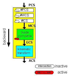
Kinematic transformation when intersection calculation is active (EcCncTrafoCtrl_cartesianTrafoInactive deleted)

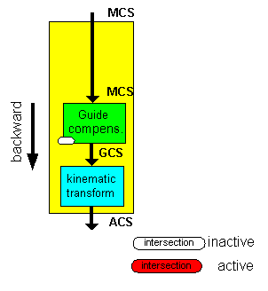
Kinematic transformation when intersection calculation is inactive
(EcCncTrafoCtrl_cartesianTrafoInactive set)
