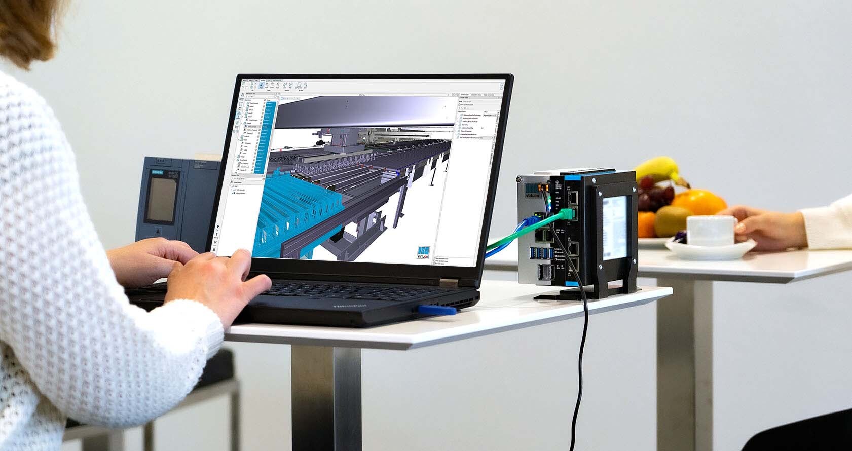
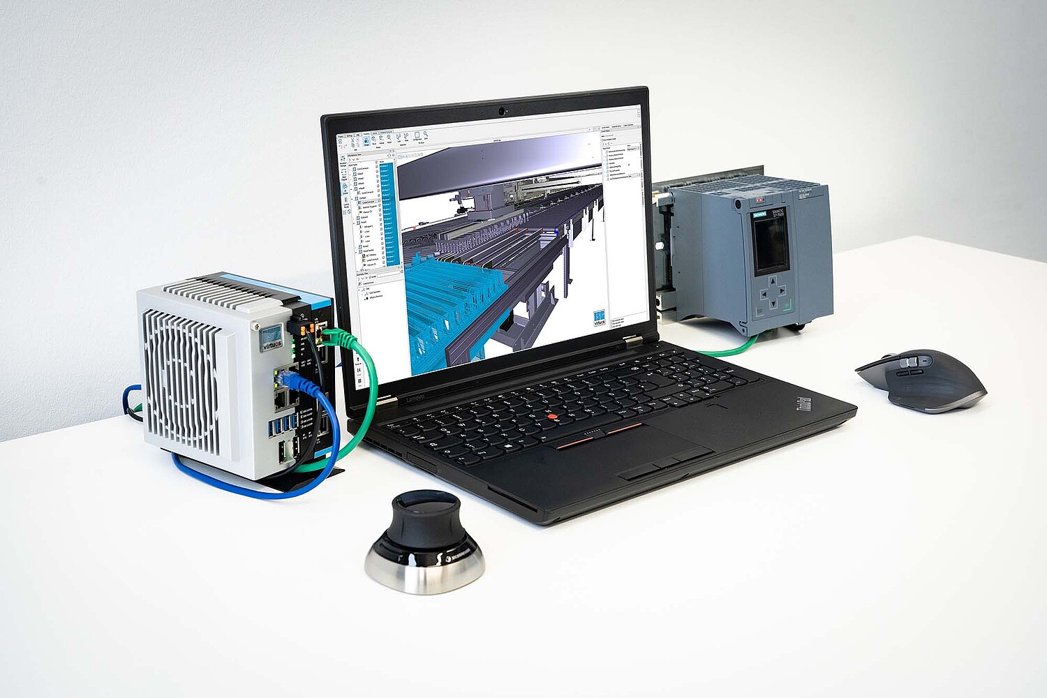
PLC / robot control level
Here the virtual system is connected to the real PLC and controlled by it. The actuator signals (control signals for motors, opening/closing of valves, proportional control of valves, ...) and control words of the PLC are interpreted and control the model. The latter sends back the sensor and feedback signals (light barriers, temperature sensors, barcodes, pulse encoder and encoder values, feedback signals of motors, limit switches, ...) to the PLC. There is no difference between model and real plant for the PLC software, the model behaves 100% like the real plant. Thus, the PLC logic can be tested before actually operating the plant.
Sequence:
Phase 1: Preparation
- For graphical modeling of new and unavailable plant components within the simulation platform, CAD data from an early phase of the design is used. If not available or not required, abstract geometry blocks are used. Depending on the project requirements, PLC (real or virtual), robot controller, control panel and other components are connected to the virtual system. The programming of the first software modules of the respective control system is carried out, interference contours and functionality are checked.
Phase 2: Implementation
- Here, assembly and implementation are carried out. For this purpose, the components simulated virtually so far (robots, conveyor technology, ...) are replaced by real components. In addition, the wiring of the system components and the first functional tests are carried out.
Phase 3: Evaluation
- Real commissioning and evaluation. PLC and robot programming are completed, and the connection of components not yet connected to the plant control system is carried out. The control software is already highly mature, only a few interventions in the programming are required.

